Arduino Safety Alert: The Right Way to Detect Live 220V Wires
Online, Monday, 18 November 2024.
As home automation enthusiasts explore Arduino-based voltage detection, safety concerns emerge. While using optocouplers offers a potential solution for monitoring 220V lines, proper isolation and protection are crucial to prevent potentially lethal accidents. Professional guidance strongly recommended for high-voltage projects.
Understanding the Basics: Arduino and Voltage Detection
Detecting whether a 220V wire is live or cut using Arduino requires a thoughtful approach to circuit design and component selection. The key to safely integrating Arduino into such a high-voltage environment lies in using components that ensure electrical isolation between the microcontroller and the power line. Optocouplers, such as the PC817, are commonly recommended for this purpose because they can effectively separate the high-voltage circuit from the low-voltage Arduino inputs, mitigating the risk of electrical shocks or component damage.
Essential Components and Circuit Design
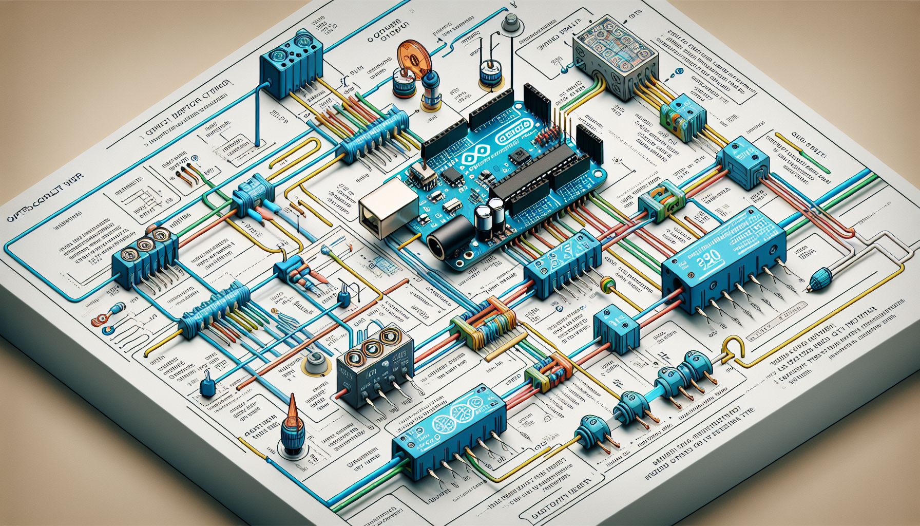
For this project, you’ll need an Arduino board, an optocoupler (PC817), a relay module, resistors (of appropriate values for current limiting), and connecting wires. The design involves using the optocoupler to detect the presence of voltage on the 220V line. When the wire is live, the optocoupler transmits a signal that the Arduino interprets as high (5V); when the wire is cut, the signal reads low (0V). This setup requires precise calibration of resistors to control the current flowing through the optocoupler, ensuring it operates within safe limits. Additionally, incorporating a relay can allow the Arduino to switch other devices on or off based on the voltage status of the wire.
Programming the Arduino: Code Snippets
The Arduino software must be programmed to read the input signal from the optocoupler and execute corresponding actions. Here’s a simple code snippet to get started:
1 | const int optoPin = 2; |
This code continuously monitors the optocoupler output and controls a relay connected to pin 3, demonstrating how to respond to different voltage states.
Safety Precautions and Best Practices
Working with high-voltage circuits demands strict adherence to safety protocols. Always ensure that the circuit is de-energized before making any connections or modifications. Use appropriate personal protective equipment, such as insulated gloves and goggles, when working near live wires. It’s advisable to double-check all connections and ensure that the optocoupler and relay are rated for the voltage and current levels they will encounter in the circuit. For those unfamiliar with high-voltage systems, consulting a professional or an experienced hobbyist can provide additional safety assurance.